
Car-park ventilation may control vehicle pollutants during normal use, clear smoke after a fire, protect escape routes or support firefighting. These are different objectives, so “car-park extract” does not by itself define the required system.
At a glance
- Confirm whether the objective is normal ventilation, smoke clearance, life-safety smoke control or firefighting support.
- Establish whether the arrangement is natural, ducted mechanical extract, impulse/jet fan, or a combined system.
- Coordinate extract, replacement air, fan duty, fire-rated ductwork, dampers, controls and emergency power.
- Use the fire strategy and smoke-control design—not air changes alone—to define fire-mode operation.
- Commission the complete cause-and-effect sequence, including standby and failure conditions.
Which car-park arrangement is being proposed?
| Arrangement | Practical distinction |
|---|---|
| Open-sided or naturally ventilated | Relies on permanent external openings and cross ventilation, subject to the applicable guidance and fire strategy. |
| Ducted mechanical extract | Uses grilles, ductwork and fans to extract from defined positions, with a coordinated replacement-air route. |
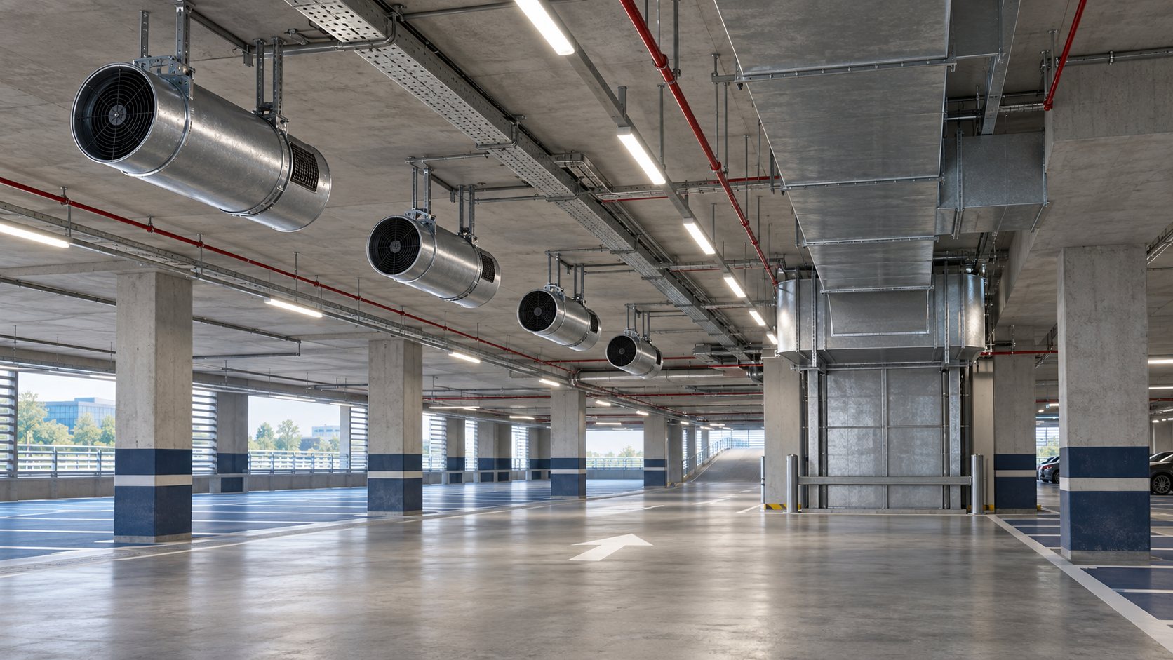
| Impulse or jet-fan system | Moves air and smoke towards extract points and may reduce distribution ductwork, but still needs effective extract and replacement air. |
| Performance-based smoke control | Uses project-specific calculations or CFD to demonstrate stated escape or firefighting objectives. |
| Combined normal and fire mode | May share equipment but uses different duties, controls and operating sequences during a fire. |
The selection must suit the car-park geometry, ramps, beams, services, compartments, escape routes and fire-service access. An arrangement used on one project should not be copied to another without design review.
How does the system normally operate?
During normal use, fans may run continuously, to a schedule or in response to pollutant sensors. In fire mode, the approved controls may start duty smoke-extract fans, operate selected jet fans and smoke-control dampers, establish replacement air, stop incompatible equipment and provide firefighter controls.
This is not a universal sequence. The fire strategy and smoke-control designer must define which components operate, their timing and duty, and the response to fan, power or control failure. The final sequence should be recorded in the cause-and-effect matrix.
Mechanical fire ventilation under England guidance
Where an enclosed car park cannot achieve the required natural ventilation, Approved Document B Volume 2 describes a mechanical route based on 10 air changes per hour in fire mode. It also describes two independent parts, each capable of 50% of the required duty, appropriate power resilience and extract points divided between high and low level.
The guidance identifies smoke-control ductwork tested to BS EN 1366-8 and powered smoke extract fan evidence to BS EN 12101-3 for this route. BS 7346-7 may provide an alternative design approach. The applicable UK jurisdiction, current edition and project fire strategy must always be confirmed.
Coordinate smoke fans, ductwork and replacement air
Smoke fans must be selected for the approved airflow, system resistance, temperature class, operating duration, mounting arrangement and controls. Jet fans create movement within the car park; they do not remove smoke from the building by themselves.
The ductwork requirement depends on its function, route, compartments served, pressure and fire exposure. A route remaining within one defined compartment may use a BS EN 1366-9 evidence route where applicable. A route serving or passing through multiple compartments may require BS EN 1366-8 evidence.
- Check duct sizes, aspect ratios and pressures against the permitted field of application.
- Keep joints, supports, access doors, flexible connections, penetrations and fire stopping within the approved arrangement.
- Coordinate fan pressure and temperature duty with the limits of the duct and damper evidence.
- Position replacement air so it supports the intended smoke path without compromising escape routes.
See the related guidance on Smoke Control Fans, BS EN 1366-8 and BS EN 1366-9.
Standards and guidance commonly encountered
| Subject | Likely reference |
|---|---|
| Covered car-park smoke control | BS 7346-7 |
| Powered smoke extract and jet fans | BS EN 12101-3 |
| Smoke-control duct sections | BS EN 12101-7 |
| Smoke-control dampers | BS EN 12101-8 and testing to BS EN 1366-10 |
| Multi-compartment smoke extract ductwork | BS EN 1366-8 / BS EN 13501-4 |
| Single-compartment smoke extract ductwork | BS EN 1366-9 / BS EN 13501-4 |
| Building provisions | Applicable national Building Regulations guidance |
The correct route is project-specific. Normal ventilation compliance does not prove fire-mode performance, and a certified fan does not certify the connected ductwork.
Design changes that require particular attention
Vehicle stackers, charging infrastructure, storage, automated parking, added partitions, service obstructions and altered escape routes can change the design basis. Where accepted guidance does not fully address an arrangement, the fire engineer, smoke-control designer and approving authority should agree the project-specific approach.
Information needed before pricing or manufacture
- Fire strategy and stated smoke-control objective.
- Smoke-control report, calculations and CFD where applicable.
- Plans, sections, zones, ramps, duct routes and discharge positions.
- Cause-and-effect matrix and normal/fire-mode sequence.
- Fan duties, temperature classes, standby and power requirements.
- Replacement-air routes and external-opening information.
- Duct classification, pressure, duration, orientation and exposure.
- Damper schedule, supports, penetrations and fire-stopping details.
- Leakage testing, commissioning, witnessing and handover requirements.
Commissioning and common mistakes
The completed installation should be tested as a system. Verification may include fan duties, airflow direction, damper positions, jet-fan sequence, standby changeover, alarm interfaces, power-failure responses, manual controls and replacement-air openings. Where CFD supports the design, the installed geometry and settings should match the model assumptions.
- Using air changes per hour as the complete smoke-control design.
- Treating pollutant ventilation as proof of life-safety performance.
- Assuming jet fans remove the need for extract and replacement air.
- Leaving single- versus multi-compartment classification undefined.
- Changing geometry without reviewing the calculations or CFD.
- Testing components without proving the complete control sequence.
Request a ductwork scope review
Send the fire strategy, smoke-control report, drawings, fan schedule and ductwork requirements for an initial review of the car-park ductwork scope.
Important: This page provides general coordination guidance only. Car-park smoke-control systems must be designed and approved by the responsible competent parties using the project fire strategy, current requirements, product evidence and an approved cause-and-effect matrix.
Source basis: BS 7346-7:2013, BS EN 12101-3, BS EN 12101-7, BS EN 12101-8, BS EN 1366-8, BS EN 1366-9, BS EN 1366-10, BS EN 13501-4 and Approved Documents B and F for England. Check the current documents and applicable UK jurisdiction.
Guidance review: September 2026. This is an original practical summary and does not reproduce or replace the relevant standards or project evidence. How this guidance is reviewed.