
BS EN 1366-9:2024 guidance
Smoke extraction ducts serving one fire compartment
BS EN 1366-9 describes the fire-resistance test method for smoke extraction ducts used only within a single fire compartment. The system is intended to operate during the developing, pre-flashover stage of a fire, represented by exposure up to approximately 600 °C.
Current edition: BS EN 1366-9:2024, which supersedes the 2008 edition. Always verify the edition required by the project and use the published standard, classification report and applicable field-of-application evidence.
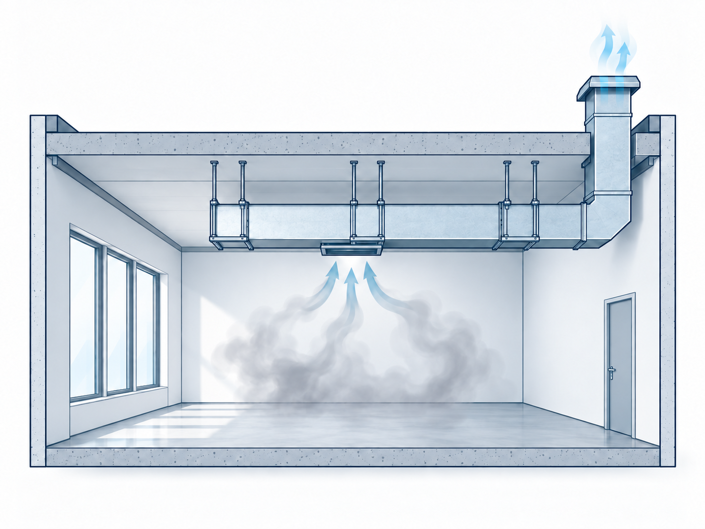
When EN 1366-9 is relevant
- The duct forms part of a mechanical smoke extraction system.
- The duct remains within the single fire compartment from which smoke is extracted.
- The proposed duct is a four-sided rectangular or circular construction made from materials within the scope of the test method.
- The route and evidence relate to a horizontal single-compartment application.
If the smoke extraction duct passes into or through another fire compartment, EN 1366-8 is the relevant test route to investigate. EN 1366-9 should not be used as a general label for every smoke extract duct.
What the test examines
Leakage before and during fire exposure
The duct is assessed under controlled pressure conditions. Leakage is measured at ambient temperature and during the fire test because excessive leakage can undermine smoke extraction performance.
Maintenance of the internal flow area
Deflection and reduction of the internal cross-section are assessed. The duct needs to remain sufficiently open to carry the intended extract flow rather than merely remain attached.
Mechanical stability
The test observes collapse, breakdown and other deformation that could stop the duct performing its intended function. Supports, joints, restraints and stiffeners are therefore important parts of the tested arrangement.
What changed in the 2024 edition?
The 2024 revision supersedes BS EN 1366-9:2008. It adds or clarifies matters including evidence for vertical sections that remain within the smoke compartment, measurement positions for cross-sectional deflection, and the oxygen-analysis arrangements used for leakage assessment. Earlier evidence should not be assumed to be directly interchangeable with the 2024 method; confirm the applicable classification and scope with the system owner or a competent specialist.
Direct-application limits matter
The field of direct application is tied to the tested temperature, duration and pressure level. Duct dimensions, suspension stresses, construction type, stiffening and any vertical section must remain within the permitted scope. Smaller or larger configurations should never be accepted solely because they look similar to the tested specimen.
When the required duct exceeds the available evidence
Current industry guidance identifies standard direct-application sizes of up to 1250 mm × 1000 mm for rectangular smoke-control duct sections and 1000 mm diameter for circular duct sections. The actual classification and system documentation may impose tighter limits.
Do not scale a tested duct construction to suit an oversized opening. Possible design responses include a battery of smaller independently evidenced ducts, a different route or system, or a project-specific technical appraisal accepted by the approving authority. The smoke-control designer must verify airflow distribution, pressure losses, fan and control strategy, while the structural design must address support loads and fire performance.
Evidence checklist for a project review
- System route: demonstrate that the duct remains within one fire compartment; otherwise investigate EN 1366-8.
- Required performance: confirm classification, duration, operating temperature and pressure level.
- Test and classification: obtain the current test report, classification report and valid field-of-application evidence.
- Duct construction: compare shape, dimensions, material, gauge, seams, joints, stiffeners, end details and any protection system.
- Supports and restraint: verify paired hanger rods, support channels, centres, loads, joint positions, restraints and any compensators.
- Route details: identify every horizontal and vertical section and confirm each is within the evidence.
- System interfaces: coordinate the duct with the smoke control dampers, smoke extract fan, controls and design documentation.
- Installation information: make sure drawings and method statements reproduce the evidenced system rather than a generic detail.
Smoke extract fans and BS EN 1366-9 ductwork
BS EN 1366-9 addresses the fire-resistance testing of single-compartment smoke extract ductwork. The smoke extract fan is a separate but connected part of the system and is normally selected and evidenced to BS EN 12101-3.
- Confirm the required airflow and system pressure, including duct resistance and leakage.
- Confirm the fan temperature/time classification, such as F200, F300 or F400, against the smoke-control strategy.
- Coordinate the fan location, flexible connections, controls and power supply with the ductwork route.
- Keep the fan and duct evidence distinct, but check that they are compatible as one complete smoke-control system.
DuctFix can discuss Elta smoke fan supply alongside a BS EN 1366-9 ductwork enquiry. Selection remains project-specific, so include the fan duty, temperature classification, drawings and control requirements in the Project Review. You can also view the Elta smoke fan range.
Common specification warning
The phrase “EN 1366-9 ductwork” does not by itself define an acceptable system. The specification should also identify the single-compartment route, required classification, pressure level, construction, dimensions, support arrangement and the evidence covering the installation.
Source basis: BS EN 1366-9:2024, reviewed for this guidance page. This is an original practical summary and does not reproduce or replace the standard.