
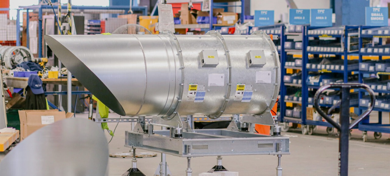
Smoke control fans are life-safety components used to move smoke and hot gases as part of a designed smoke-control system. The correct fan cannot be selected from airflow alone: duty, pressure, temperature class, operating time, controls, power supplies and installation arrangement must all be coordinated.
What standard applies?
Powered smoke and heat control ventilators, including ducted smoke extract fans and impulse or jet fans, are covered by BS EN 12101-3. A fan should be selected as part of the complete smoke-control design, with current product evidence demonstrating that its declared performance suits the project duty and operating scenario.
Temperature and operating duration
Smoke-control fans are available with different high-temperature performance classifications, commonly including F200, F300 and F400 categories. The designation relates to operation at a stated temperature for a stated period; it is not a general indication that the highest available number should always be chosen.
The required classification must come from the fire strategy and smoke-control design. Product certification, installation orientation, motor arrangement and any limitations should be checked for the exact fan proposed. Normal ventilation duty and emergency smoke duty should also be distinguished: some installations use the same equipment for both, but that does not remove the need for the correct emergency classification and control sequence.
Ducted, impulse and induction systems
Ducted smoke extract fans create the pressure required to move smoke through a defined ductwork route. In enclosed car parks, impulse or induction fans may instead create high-velocity air movement that entrains the surrounding air and directs smoke towards extract points. This can reduce the amount of distribution ductwork, but it does not make the system a simple collection of independently selected fans.
Fan locations, thrust, make-up air, smoke reservoirs, structural obstructions, escape routes and extract points must be developed as one system. Calculations or CFD may be needed to demonstrate performance. See the separate guidance on enclosed and basement car-park smoke ventilation.
Evidence to check before selection
- Required volume flow and external static pressure at the design duty point.
- Declared temperature class and operating duration to BS EN 12101-3.
- Whether the fan is inside or outside the smoke reservoir or fire compartment.
- Fan orientation, mounting arrangement, location, ambient conditions and maintenance access.
- Duty/standby philosophy, primary and secondary power, controls and cause-and-effect requirements.
- Compatibility of any variable-speed drive, starter, isolator, cabling and control arrangement with emergency operation.
- Acoustic requirements, attenuators, weather protection and the final discharge arrangement.
Coordinate the fan with the ductwork
The fan duty must include the resistance of the complete route, including smoke-control ductwork, bends, transitions, attenuators, dampers, grilles and discharge arrangements. Duct classification, leakage, pressure limits, supports and compartment crossings should be checked against the relevant system evidence.
A certified fan does not certify the connected ductwork, and tested ductwork does not prove the fan selection. Their operating limits must be coordinated so that the fan does not impose a pressure, temperature or movement condition outside the duct and damper evidence. See the guidance for BS EN 1366-8 multi-compartment systems and BS EN 1366-9 single-compartment systems.
Controls and prefabricated assemblies
Smoke-control fans depend on the fire alarm interface, dampers, control panels, power supplies and final cause-and-effect logic. Prefabricated fan, control or support assemblies can reduce site interfaces and installation time, but the completed arrangement still needs suitable certification, safe access, coordinated interfaces and project-specific commissioning.
Information needed for a useful enquiry
- Fire strategy and smoke-control design objective.
- Design airflow, pressure and each required operating scenario.
- Required temperature and duration classification.
- Duct sizes, route, resistance calculation and discharge location.
- Electrical supply, controls, standby arrangements and cause-and-effect matrix.
- Space, access, mounting, acoustic and maintenance constraints.
Source basis: BS EN 12101-3 and published manufacturer technical information concerning ducted, impulse, induction and high-temperature smoke-control fans. This page is general coordination guidance, not a smoke-control design or product selection. The fire strategy, calculations or CFD, product evidence and complete system arrangement must be reviewed by the responsible competent parties.
Guidance review: September 2026. This is an original practical summary and does not reproduce or replace the relevant standards or project evidence. How this guidance is reviewed.